5GHz/6cm Radio Link DK0SG
- DK5EC
with low-cost WLAN and Junk Yard Components
Author: Karl, DK5EC, dk5ec @ darc.de
Motivation
Amateur radio has been enhanced tremendously by the use of the internet during th last 2 decades. Some radio operating modes, like WSPR or EME/WSJT, are not even possible without the use of the internet. The internet even enhances the operation of some traditional analogue modes, i.e. dx-cluster or qrz.com. Because of that we missed an internet access at our remote club station since many years. Partially we tried to use the usb surf sticks enabling an internet access via EDGE/UMTS/HSPDA of some mobile providers. But our club station is in the country side where these providers do not deliver the necessary signal strength for a fast data access. EDGE normally works, but UMTS and HSPDA normally not. With these conditions, the idea came up to build an internet access by means of a broadband radio link to one of our nearby club members.
Jochen, DL1YBL, lent us a pair of Motorola Canopy Ethernet bridges, which he already used to put up radio links for some of the amateur repeaters at remote areas in his responsibility. These bridges have everything integrated in one housing, that is, transceiver, antenna, ethernet lan, web interface. The output power reaches only 100 mW (legal limit) and an antenna gain of 6 dBi. We set up these units at DK5EC's and DD9KA's (Heinz) homes (line of sight), and we were able to communicate and to use each others internet over a distance of 2 km. However, when raining, the data rate became rather low or the connection broke down completely. Anyway, Jochen needed his components again, and we had to return them.
Heinz told me to look up the site of Ubiquiti. There, I found a tremendous selection of WiFi and radio link components, and according the specifications their functions were rather similar to the tested Motorola Canopy components. When checking the prices of these gadgets with some of the local dealers, I immediately ordered two units Ubiquiti NanoStation5 Loco (5 GHz, low-cost) for a mere € 55.- each. These apparent no-name products were in the range of my low pensioners' budget, and if they were no good for that cheap price, I could have survived it.
Putting into operation of the hardware
2 days later, the mail man brought me a very small package. First I became angry, believing that the dealer had sent me only one unit. But no, the small package contained the 2 units, including the additional the PoE power supply. This Power-over-Ethernet unit enables the power supply of the outside installed unit via the ethernet cable.
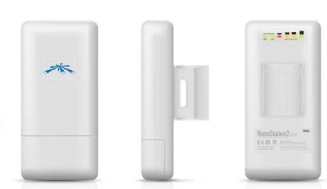
NanoStation5 LoCo
These units have external sizes of 13 x 8 x 3 cm only, with a mere weight of 180 g. The left figure shows the unit in the direction of radiation, the square with the blue symbol represents about the antenna size (see below). According to specification, the antenna has a gain of 13 dBi. The lower part is detachable for the ethernet cable connection. The housing is (hopefully) weatherproof. The center figure shows the clamp for mounting the unit to a pipe. The back of the unit (left figure) contains a LED row as status indicators for power supply, LAN connection and receiver signal strength.
At my desk at home, I set up a test link with two notebooks and the two NanoStations. And then the first blow. Desperately I was looking for a manual or at least a CD in order to be able to put it into operation. They didn't deliver anything! After looking at the cartons I discovered a small hint to call up the browser interface with the IP 192.168.1.20 first. After adjusting my two notebooks to IPs within the same IP range I could see the excellent configuration menus at my browser, and my initial disapointment was more than compensated.
User Interface and Configuration
After setting up my 2 notebooks to nearby IP addresses I entered the IP 192.168.1.20 into the address field of the browser, the following user interface and configuration menu appeared.
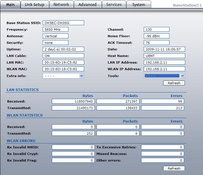
Main menu, configured as Access Point
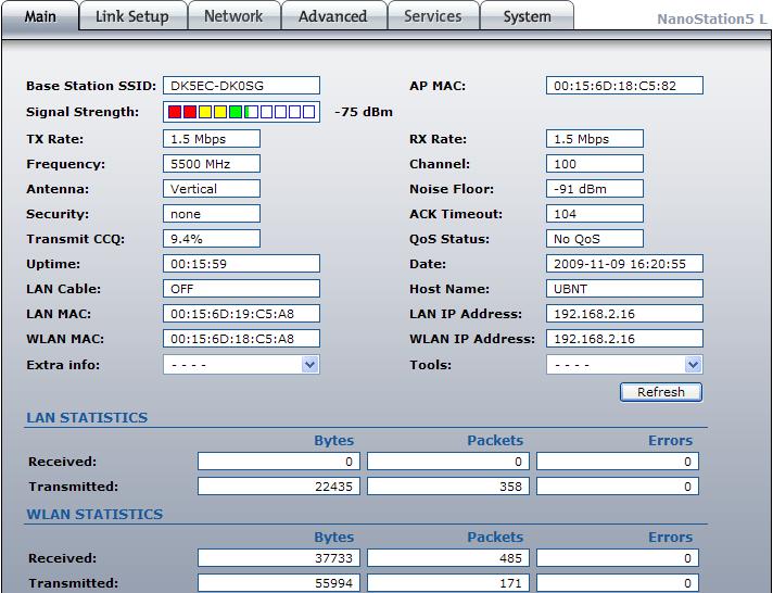
The Main menu shows the current configuration status of the NanoStation5. The values only can be altered in the other menus, but not here. This unit is configured as an Access Point. The following figure shows the same Main menu, the unit here is configured as a "station", that is, a WLAN client.
Main menu as WLAN Client
With the help of the signal strength indication the antenna direction may be adjusted. In order to catch the changes you have to press the Refresh button very often. When using the Access Point unit you have to call up the Tools submenu, then Align Antenna, to have a comparable indication. The signal strength should be more than 10 dB above the Noise Floor value in order to guarantee a decent data throughput of 1 MBit/s or more.
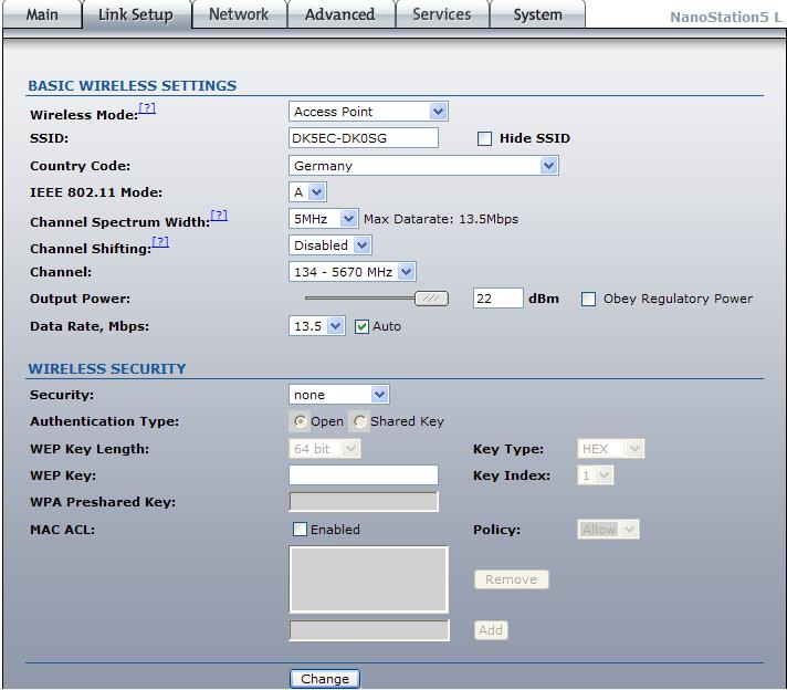
Configuration menu Link Setup
With the help of the menu Link Setup, several parameters may be configured. The main station, that is the one near the internet router, should be configured as an Access Point. The WLAN client is configured as Station. Even if no DSL router or internet is used, one unit always has to be configured as Access Point so that the WLAN client is able to get the necessary frequency information.
When using the units as a 6cm link between radio amateur stations, the SSID should contain the call signs of these two stations. I configured the units to the lowest possible Channel Bandwidth of 5 MHz, enabling the highest signal strengths. Since my DSL connection runs on a maximum of 2 MBit/s only, a higher bandwidth would be counterproductive. When using the 40 MHz bandwidth, the available radiated power of 100 mW would be distributed over this bandwidth, that is only 2,5 mW/Mhz. When using only 5 MHz bandwidth, the radiated power is 15 mW/MHz, that is, 8 times higher. When testing the link DK5EC - DD9KA (line of sight, no objects in between) we could easily operate the 40 MHz, achieving data throughputs of 20 MBit/s. The attenuation of the link DK5EC-DK0SG is quite higher because of the longer distance and objects in between which may cause additional deterioration up to -25 dB.
We choose the frequency of 5670 MHz (channel 134), that corresponds to the DARC band plan for link stations. However, the power budget is about 5 dB weaker than in the in the center of the available frequency range of the NanoStation. Even though the use of the 100 mW is free within the whole band range, we effectively use more than 10 W ERP when adding the antenna gains. Under these circumstances in Germany we are confined to use only the frequencies assigned for amateur radio bands, and that is above 5600 MHz.I adjusted the power output to the maximum of 22 dBm, that is about 150 mW. I am using WPA2 encryption, even though there is a contradiction. On one hand, encryption within amateur radio is forbidden. On the other hand, when using the internet I am obliged to use encryption. Well, I think if the authorities always can read the non-encrypted SSID, they can ask me for the encryption key.
Configuration menu Network
This menu enables you to adjust the Network Mode (mode Bridge for both sides) and the IP address of the NanoStation5. My DSL router has the IP 192.168.2.2, hence the units must operate within the same address range. These addresses are entered as static. Make sure that these addresses are outside the DHCP range of the DSL router, otherwise you might encounter address conflicts. The Gateway and DNS IP should contain the IP address of your DSL router. Without theses entries the internet access cannot be found.
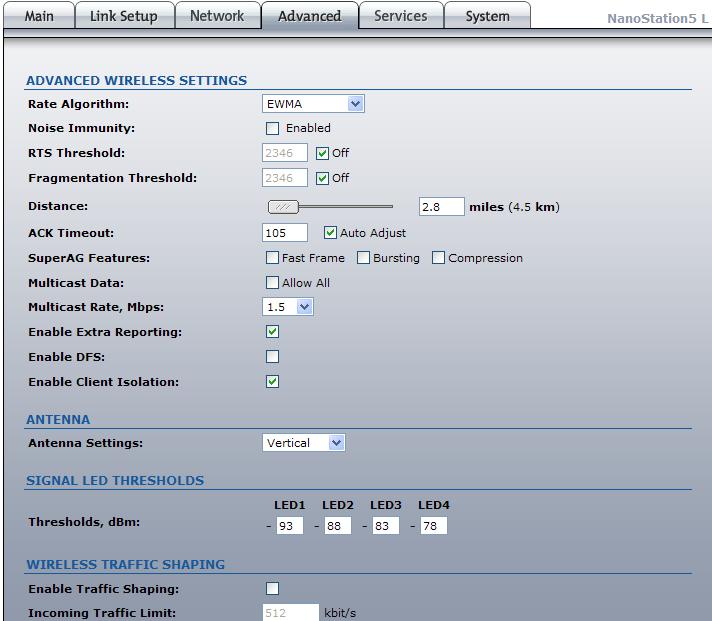
Configuration menu Advanced
When using the menu Advanced, you may enter the approximate link distance. Most probably the signal delay may be considered here.
The antenna polarisation Vertical proved to be about 5 dB better than Horizontal.
Under Thresholds you may adjust the signal strength LEDs at the back of the units to a desired threshold level.
General Hints for the configuration
Principally, you may configure the opposite link station from one side and may change parameters. But you should know that you also may disconnect yourself unvoluntarily when changing certain values of the opposite station. Make sure that you always change the value of the opposite unit first, than enter the same value at the local unit. In a third step verify that the two stations can still communicate. Make sure that the parameters on both sides are 100 % identical, of course except the IP address and the Wireless Mode. At the "Station" side you can not adjust the frequency because it will be derived by the Access Point automatically.
Test and Diagnosis
Calling up the menu Main and the buttons Extra Infos and Tools, variable tests and diagnosis of the units and link performance may be performed. The following figures show some examples.
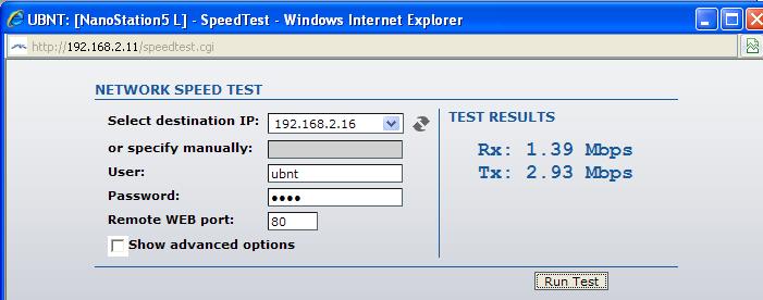
Tools/SpeedTest, data throughput of the radio link
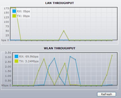
Extra Infos/Show Throughput, data throughput of the radio, the LAN link and total link
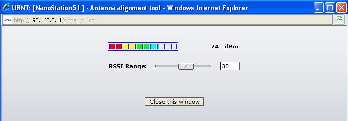
Tools/Antenna Align, real-time signal strength indicator for antenna adjustments
Configuration of the WLAN Clients (Computer)
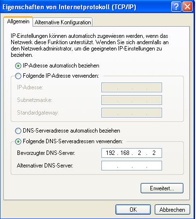
network configuration of the computer
When configuring the WLAN Client make sure that you have entered the favourite DNS Server and the IP address of the DSL router. Otherwise, internet communication is not possible. The computer sees the radio link just as a LAN cable extension, working as a bridge.
Calculation of the Link Budget
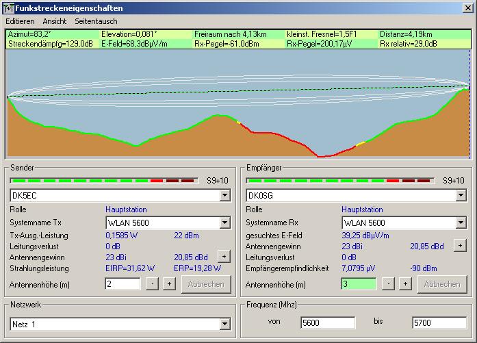
The excellent software Freeware Program Radio Mobile has been used to calculate the link budget of the radio link. The following parameters were used for both stations:
Transmitter power: 22 dBm
Cable loss: 0 (since Antenna is connected to the transceiver directly)
Antenna gain NanoStation: 13,5 dbi (built-in antenna NanoStation5 LoCo)
Antenna gain of the dishes: ca. 10 dB
Link distance: 4,19 km (will be calculated by the software)
Calculation of the Link Budget DK5EC - DK0SG
When calculating the link budget, regard the transmitter power and the antenna gain with a tolerance of +/- 2 dB. Considering the signal/noise ration of 29 dB, more than enough signal reserve for a reliable link would have been available. However, the calculation only considers the direct line of sight view. Additional attenuation caused by several rows of trees was measured after link establishment, and was about 12 ...23 dB. With the resulting link budget of -73 ...-83 or SNR of 7 ...17 dB we could reach a data throughput of about 1...3 MBit/s. That proved to be more than enough for our radio amateur purposes, needing only low data quantities when operating WSPR, WSJT, DX cluster or search engines.
During strong rain fall and fog the data throughput deteriorated considerably, sometimes the link broke down. At night times, the signal rates are lower than at day time; I suppose this is due to the higher humidity at night. At a later time we still have to see how the link works in winter, we hope for a better link because of the fallen leaves of the trees in the line of sight. Anyway, in spite of these restraints, we are happy that it works at all because we were afraid that the trees were fatal for the 5,6 GHz link. But the junk yard satellite dishes compensated the attenuation.
Adjusting the Reflectors (junk yard TV satellite dishes)
As you could see from the link calculation diagram and the expected attenuation cause by the trees, a reliable operation of the radio link without additional antenna gain by the reflectors would not have been possible. The additional gain caused by the dishes proved to be absolutely necessary.
Ubiquiti sells some reflectors, but not in combination with the inexpensive NanoStation5 loco. In order to by all necessary ready made products for a reliable link we would have spent several €100.- more. Not having that left over money, but more because of the honor as a genuine radio amateur, we found a solution for € 0.00, which is about $ 0.00 or less.In my private junk yard I found 3 old TV satellite dishes. Since I thought I would be really hard to overcome the attenuation caused by the trees, I started with the biggest dish, measuring 130 cm in diameter. At the other side of the test link I put up the other NanoStation5 in my yard, about 45 m apart, without dish. First I took out the old TV LNB (11GHz), and by trial an error I found the focus for my 5GHz NanoStation. Surprisingly I found out that position of the focus was absolutely uncritical. I could move the Nanostation 5 cm back an forth to the dish, and I hardly could notice any change in gain. The vertical position of the NanoStation was also not critical because I could compensate this afterwards later by changing the angle of the whole dish. As an optimum I could reach about 11 dB gain. I must admit I was a little bit disapointed, I expected more from this huge dish. The measured 11 dB gain is only an approximate value since I did not have any high grade signal measurement equipment, I relied on the field strength indication of the NanoStation user interface. Well, the actual dB values actually are not that important to me, I just wanted to find out the possible optimum.
At first, I did not understand why the precise position of the LNB (now the NanoStation) could not be determined, but after a while thinking about it I found the reason. A regular TV satellite dish uses a LNB for 11 GHz, containing a simple small dipole having a receiving surface of about 15 x 2 mm, that is, about 30 mm². In contrary, the NanoStation5 has (apparently) several stacked dipoles being distributed over an area of about 600 mm², and that is the 20-fold receiving area of the TV LNB. Hence, because of this bigger receiving antenna surface, the focus for the NanoStation5 is about 20times less precise than for the small dipole of a TV LNB.
As the next step I took the handier 80 cm TV offset dish. Here I had to dismount the TV LNB out of the rusty screws and to do some mechanical works because the mount allowed a minimum of 20 degrees elevation. For my terrestrial radio link I need 0 degrees. Anyway, with this smaller dish I also made the same experience regarding the inaccurate focus, and the maximum gain I could achieve with this dish was about 10 dB.
As the third step I tested the 60 cm dish. I noticed the same inaccurate focus as with the other dishes. Surprisingly the antenna gain was about the same as with the two bigger dishes.
My feelings actually told me, the bigger the dish, the higher the gain. But this is only true when using an isotropic radiator. The NanoStation5, however, has an integrated directional antenna with about 13,5 dB gain with a radiation angle of 45 degrees, that is, 22,5 degrees left and right there is already a loss of 3 dB, with bigger angles the loss increases rapidly. With other words, larger dishes can only be covered partially by the rather narrow radiation angle. Just for a test, when covering the right quarter of the dish with my body I could notice a mere loss of 1 dB in signal strength. With my mechanical constructions of pipes and shortwave tower I had to mount the dish this way that the mast covered the radiation field of the dish by about 10 cm, but that practically had not caused any loss.
NanoStation5 Loco with reflector at DK5EC's site
The picture above shows the 80 cm reflector with the NanoStation5 as a LNB unit. The NanoStation5 has been fixed to the existing bracket of the TV dish by tape and cable strap. The additional small wedge between the bracket and the unit gave the right angle, so that the NanoStation5 right angle points towards the center of the dish. Most probably the 80 cm is rather oversized, but the poor pensioner takes what he has. The Versa Tower covers about 10 cm of the radiation field of the dish, but the losses are hardly noticeable.
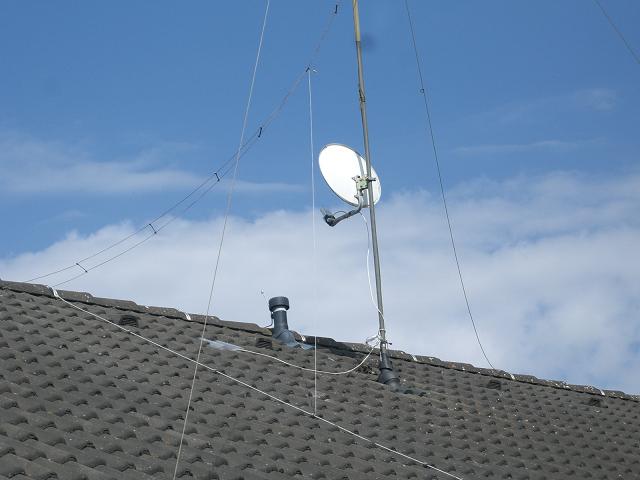
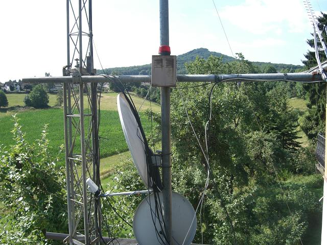
NanoStation5 at the club station DK0SG
The above picture shows the opposite side at the roof of the radio club with its 60 cm reflector. About 200m apart, in direction of DK5EC, a small wood about 50 m wide covers the line of sight causing 10...25 dB additional link loss, depending on environmental conditions (moisture, wind, winter/summer).
Anyway, the experiments with the old dishes were actually the most interesting works of the whole project. For me it had been my first experience with dishes and radio links, and I could learn a lot. Even not using any professional measuring equipment the final result was quite presentable. The excellent but simple possibilities for measurement and diagnosis of the NanoStation5 were completely sufficient for these experiments and final successful establishment of the radio link.
Complete Scematic Diagram
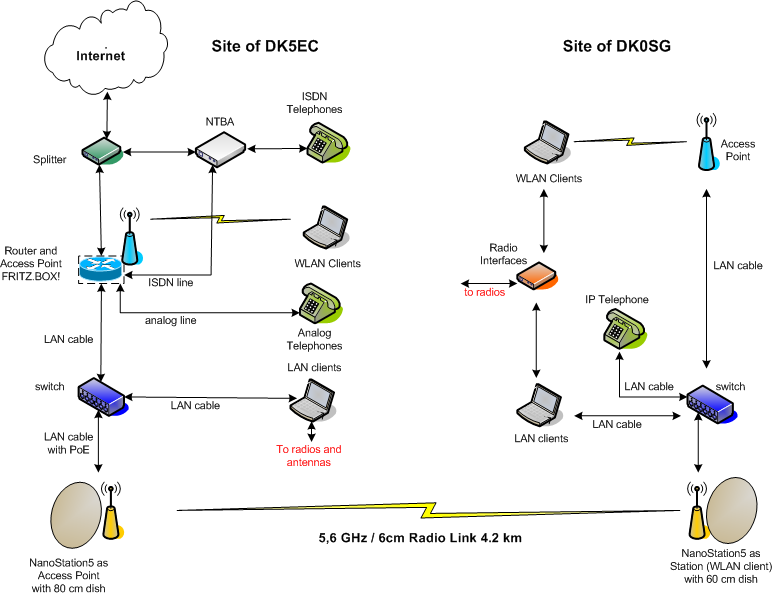
Complete scematic diagram of the DK5EC - DK0SG connection
The above diagram shows all components of the complete link including peripheral equipment. The telephones at the side of DK5EC are actually not involved and shown only for completeness. The IP telephone at the side of DK0SG is only temprorarily connected because of legal reasons. It will be used mainly for teaching purposes because we intend to teach modern internet technologies as well, besides the usual radio stuff. The equipment of DK5EC can be remote-controlled. Hence it is possible to use DK5EC's satellite and EME station at the site of DK0SG. Anyway, the new radio link opens a wide field of new technologies adding very interesting aspects to our hobby.
Summary
Hard to believe, but for a mere € 110.- and a couple of junk yard components a highly efficient broadband radio link via 4.2 km plus additional enviromental attenuation could be established. A couple of years ago you had to pay a couple of € 1000.- for commercial components for such a link, or experienced radio amateurs with a very good knowledge of microwave technology could have achieved that and spending a lot of time.
I really was thrilled by the scope of functions offered by the NanoStation5:
1. very simple and logical menus, usable by non professionals
2. all necessary means for testing and diagnosis, including antenna alignment and throughput measurements, are included. No additional test equipment is necessary.
From the point of the radio amateur the decrease in efficiency when using the upper frequency range was a disadvantage because the amateur bands start at 5600 MHz. On the other hand the equipment also suits very much the needs of non radio amateurs needing a reliable short-range radio link for internet access staying within the limits of the legal 10 mW ERP.
Surprisingly I could use old junk TV satellite dishes for my experiments not having any previous knowledge, just by trial and error. As a radio amateur that was most rewarding to me.